
The University of Southern California’s Norris Healthcare Center (HC3) is a seven-story, 116,000-sf OSHPD 3 healthcare center (with OSHPD 1 components) designed to prioritize patient privacy and comfort as its top priorities. The building houses a variety of departments and services, including urology, women’s specialty care, breast imaging, transplant, an infusion center, and an outpatient surgery center. The HC3 is part of Keck Medicine of USC, which is ranked among the top five hospitals in California by U.S. News & World Report’s Best Hospitals.
The seven-story steel frame building (including a one-story basement) was designed and constructed to LEED Silver standards and the 2011 edition of City of Los Angeles Building Code. The gravity system of the building consists of 3” corrugated metal decking with 3-1/4” light-weight concrete fill for a total thickness of 6-1/4” in all areas except at the loading dock area on the southeast corner of the building. At the loading dock area, 3” corrugated metal decking with 7” normal-weight concrete fill for a total thickness of 10” was used. The decking in all instances is supported by steel wide flange purlins spaced no more than 10’-6” on center. The beams include welded shear studs at the top flange to engage the concrete deck for composite action. The steel purlins are supported by wide flange steel girders, which in turn were supported by wide flange steel columns.
The lateral force resisting system (LFRS) of the structure consists of the concrete on metal deck acting as the horizontal diaphragm, which transfers lateral forces to the vertical lateral load resisting elements. The vertical lateral load resisting elements consist of reduced beam section (RBS) steel special moment frame (SSMF) system in each orthogonal direction. A 3D structural analysis model of the outpatient structure was created using RAMSTEEL for the gravity design. For the lateral analysis of the structure, a 3D analysis model in ETABS was created. A dynamic response spectrum analysis was performed for the lateral analysis and design of the structure. W27x and W30x beams, and W27x columns were used for the SSMF. As a few columns were part of SSMF acting in both directions, cruciform columns were used for those conditions. The foundation systems of the structure consist of a combination of pile foundation and individual spread footing. The northern half of the structure was supported by pile foundations and the southern part was supported by the individual spread footing and combined footing. The fixity of SSMF column was obtained by embedding the columns into the 48” deep grade beams and by welding grade beam reinforcement to the frame column flange.
The IMEG structural team solved several challenges, including:
- A 17’-6” high cantilever retaining wall was located on the west, north and partial east side of the basement. The building would create Extreme Torsional Irregularity, which is not allowed by the code, if the basement concrete walls were part of the main structure. To mitigate this condition, the concrete retaining wall was not positively connected to the ground floor elevated deck (concrete on metal deck). A sliding connection at the top of wall was provided.
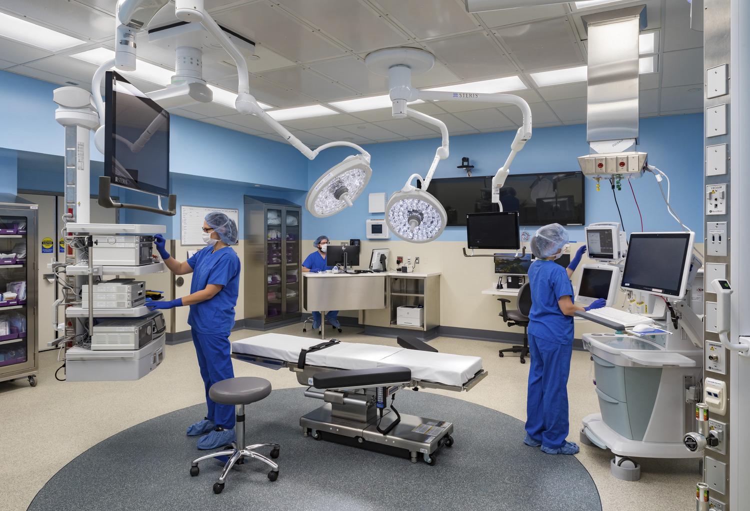
- The loading dock on the southeast corner of the structure was located right above the ORs, which have medical equipment sensitive to the vibration of the structure. This part of the structure consists of 3” corrugated metal decking with 7” normal-weight concrete fill for a total thickness of 10” thick deck system. The typical 31’-0” span in this area was reduced to 24’-1 ½” by adding one-story posts. The gravity beams and columns were carefully designed and provided based on the vibration consultant’s recommendations.
- Because of the narrow and long configuration of the structure, several columns were considered part of the LFRS for both orthogonal directions. As per the code, either a built-up box column or cruciform columns needed to be used at these locations. IMEG engineers decided to use cruciform columns in these locations. The challenge was the detailing of the grade beam rebars at the cruciform column conditions where two grade beams intersect each other. Three rows of rebars were welded to the columns and continuity plates were provided to ensure transfer of the moment from the columns to the grade beams.